


How to plan ventilation for a 300 kW containerized gas generator set
How to Plan Ventilation for a 300 kW Containerized Gas Generator Set
Ventilation for a 300 kW containerized gas generator set is often treated as a fan-selection exercise. That is where many projects begin to drift off course. A container is a confined thermal system containing an engine, alternator, radiator package, exhaust components, gas train, control panels, cable routes, and acoustic treatment. Every one of those elements affects airflow resistance, temperature rise, or safety.
For technical evaluation, the key question is not simply, “How much air can the fan move?” It is whether the installed system can deliver the required air volume at the real operating static pressure, in the hottest expected ambient condition, without recirculating radiator discharge air or creating unsafe gas accumulation zones.
The phrase 300kW Containerized gasgenerator set may describe the electrical output, but it does not provide enough information to size ventilation on its own. The engine’s heat balance, cooling arrangement, fuel gas composition, altitude, radiator design, enclosure geometry, and local installation conditions all need to be reviewed together.
Start with the Heat Rejection Path, Not the Fan Catalogue
A gas generator converts only part of its fuel energy into electricity. The remaining energy leaves through exhaust gas, engine coolant, charge-air cooling where applicable, lube oil cooling, radiation from hot surfaces, and other losses. In a containerized system, the cooling circuit is usually the dominant ventilation driver, particularly when the radiator is installed at one end of the enclosure and discharges air through a dedicated outlet.
The generator manufacturer should provide the radiator airflow requirement, allowable external resistance, coolant heat rejection, maximum ambient rating, and expected fan performance curve. These figures should be treated as the baseline. Estimating airflow from electrical output alone can produce a design that appears adequate on paper but fails during high-load operation in summer.
For a rough engineering check, sensible heat removal can be related to airflow, air density, specific heat, and permitted temperature rise. However, the permitted rise is a project decision rather than a universal value. A narrow temperature rise demands more air and larger openings; a wider rise may reduce airflow but can raise internal equipment temperatures. The radiator supplier’s limits and the enclosure component ratings should settle that trade-off.
Do not combine all airflow needs into one unexplained number. At minimum, separate the following:
- Radiator cooling airflow and discharge direction;
- Engine combustion-air demand;
- Alternator and control compartment cooling requirements;
- Heat released inside the container from engine surfaces, exhaust piping, and auxiliaries;
- Any dedicated ventilation required for a gas valve train or electrical room.
Combustion air is especially easy to overlook. The engine must receive clean air at an acceptable inlet temperature and pressure. Pulling combustion air from the hottest part of the container can reduce available power and worsen operating margins. In dusty oilfield or industrial locations, filtration also adds pressure loss over time, not just when the filters are new.
Design the Air Route Before Choosing Louvers
A workable airflow route is usually straightforward: cooler outdoor air enters through protected intake louvers, passes across the engine and auxiliary equipment, then exits through the radiator or dedicated exhaust openings. In practice, the route becomes complicated when intake and discharge openings are too close, air must turn around partitions, or acoustic baffles consume more free area than expected.
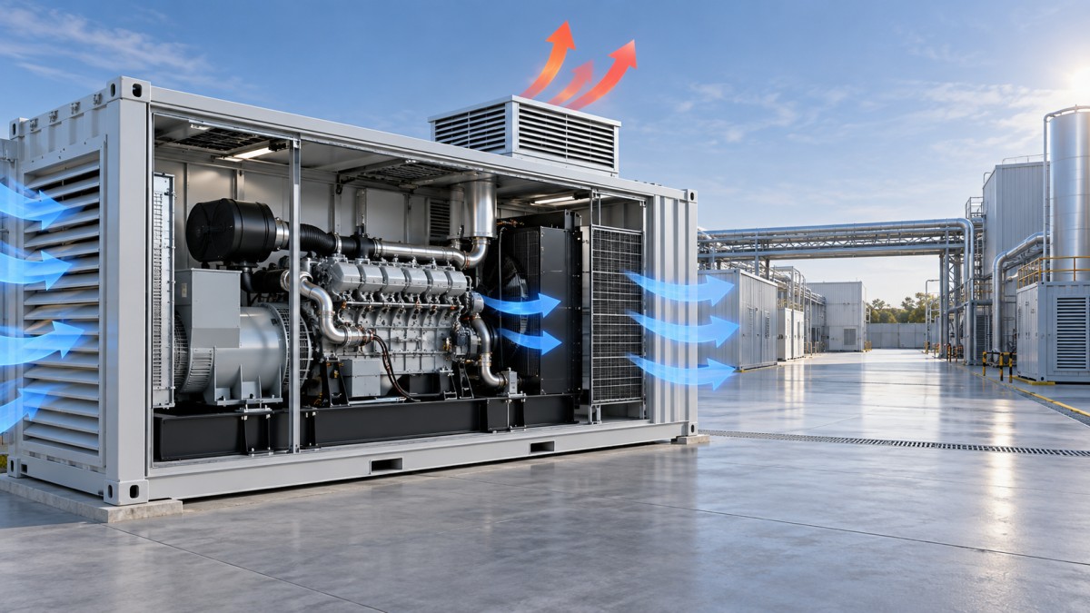
The biggest layout risk is hot-air recirculation. If radiator discharge is drawn back into the intake, the generator effectively operates in a higher ambient temperature than the weather station reports. This problem is common where containers are placed near walls, beneath canopies, inside narrow equipment yards, or in multi-unit power stations. A clean-looking installation can still have poor thermal behavior if the discharge plume has nowhere to escape.
During review, trace the air path outside the container as carefully as the path inside it. Consider prevailing wind, adjacent containers, parapet walls, cable trenches, and roof overhangs. Where several generator sets operate in parallel, one unit’s hot discharge should not become another unit’s intake air. Site CFD analysis may be justified for dense layouts, but even without it, scaled drawings and clear separation logic can expose obvious recirculation risks.
Louvers should be selected by effective free area and pressure-loss performance, not their nominal opening dimensions. Bird mesh, weather hoods, dust screens, sand traps, silencers, and dampers all reduce free area. A louver that seems generous from the outside can become restrictive after these accessories are included. High intake velocity also increases noise, pressure drop, and the chance of rain or dust being carried deeper into the enclosure.
Static Pressure Is Usually the Deciding Factor
Fan duty must be checked at the complete system resistance, not at free-air flow. The resistance budget should include intake louvers, insect mesh, filters, acoustic splitters, bends, radiator core resistance, discharge louvers, ducts, and any future fouling allowance. Pressure losses rise sharply as airflow velocity increases, so a small reduction in opening area can have a surprisingly large effect on delivered flow.
This matters most when the container uses an engine-driven radiator fan. Such fans have a defined capability, and they may not tolerate an enclosure design with excessive restriction. Adding a silencer or weather louver late in the project can shift the operating point enough to impair cooling. If electrically driven extract fans are used, their controls, redundancy philosophy, power supply, failure alarm, and behavior during emergency shutdown also need to be agreed early.
A practical review asks for a pressure-loss calculation and compares it with the radiator fan curve or ventilation fan curve. It should also identify the condition being assessed: clean filters, dirty filters, rated load, maximum site ambient, and the most restrictive damper position. A calculation without stated assumptions is not a reliable acceptance basis.
Account for Ambient, Altitude, and Seasonal Operating Modes
High ambient temperature reduces cooling margin. High altitude further changes air density and can affect both heat transfer and engine performance. These conditions should be addressed using the engine and radiator supplier’s site-derating documentation rather than generic correction factors copied from an unrelated project.
Cold climates create a different challenge. A container designed only for hot-weather ventilation may overcool the engine at low load, encourage condensation, or make it difficult to maintain a stable internal temperature. Motorized dampers, radiator shutters, variable-speed fans, thermostatic controls, and enclosure heaters may be considered depending on the operating duty. The important point is coordination: ventilation controls must not fight the engine cooling controls.
For gas power projects with variable load, review the low-load condition as well as full load. A container can be acceptable at rated output but uncomfortable for electronic controls during long periods of partial load if airflow paths or control setpoints are poorly arranged.
Safety, Gas Detection, and Maintainability Need Their Own Review
Natural gas is lighter than air under normal conditions, so any credible leak assessment must consider where gas could migrate and accumulate within the container or roof space. Ventilation openings, gas detectors, emergency shutdown logic, electrical equipment selection, and local hazardous-area requirements should be reviewed as one system. The exact requirements depend on the project jurisdiction, applicable codes, and gas system arrangement; they should not be assumed from a standard container drawing.
Maintenance access also affects long-term ventilation performance. Filters that cannot be replaced easily tend to be left in service too long. Screens clog, louvers collect debris, and acoustic materials can deteriorate in harsh environments. Provide accessible inspection points and specify what operators should check: differential pressure where fitted, fan status, damper movement, enclosure temperature trends, and visible signs of discharge-air recirculation.
For projects that standardize several capacities, comparisons with a 250KW natural gas generator set can be useful, but ventilation details should not simply be scaled by generator rating. Container dimensions, radiator selection, acoustic targets, and engine configuration can change the airflow system substantially.
What to Request Before Approving the Container Design
A sound technical submittal for a 300 kW containerized gas generator should include the ventilation layout, airflow direction arrows, louver free areas, radiator and fan curves, system pressure-loss estimate, design ambient condition, allowable internal temperatures, and control philosophy for fans or dampers. It should also show the external clearance requirements needed to prevent recirculation.
AMICO’s work in gas power control, generator equipment, oilfield services, and distributed energy reflects why this coordination matters: ventilation is not an isolated mechanical detail. It interfaces with engine performance, power controls, acoustic treatment, site construction, and operating practice. A container that is properly ventilated on the drawing should remain serviceable after filters load, weather changes, and the generator runs at real duty cycles.
Before release for fabrication, confirm one final point: the airflow calculation must match the actual container configuration, not an earlier layout with fewer baffles, shorter ducts, or larger openings. That single check prevents a large share of avoidable overheating problems after commissioning.

Contact Us
Please use the form below to contact us.
If you require a response, we will contact you as soon as possible.