


How much site space does a 1000 kW containerized gas genset require?
Evaluating the site footprint of a 1000kW Containerized GasGenset involves much more than reading the dimensions on a container drawing. For technical assessors, the container itself is only the starting point. The final plot must also accommodate service access, cooling-air movement, exhaust routing, gas conditioning equipment, electrical interconnection, fire separation, and the practical realities of bringing a heavy module onto site.
In many industrial, oilfield, and distributed-energy projects, the question is not “Will the genset fit?” but “Will it remain accessible, safe, and reliable after the civil works, pipework, cable trenches, and ancillary skids are installed?” A layout that appears compact on a proposal drawing can become difficult to operate once doors cannot open fully, radiators recirculate hot air, or an exhaust stack conflicts with nearby structures.
Start with the container footprint—but do not stop there
A 1000 kW gas generator package is commonly housed in a 40-foot container or a purpose-built acoustic enclosure of comparable length. A standard 40-foot container measures approximately 12.2 m long by 2.44 m wide, creating a physical footprint of about 30 m². A high-cube or engineered generator enclosure may be taller and slightly wider, depending on the cooling system, acoustic treatment, switchgear arrangement, and gas train design.
Those dimensions describe the transportable module, not the required operating area. For early-stage planning, assessors should separate the project into three layers:
- Equipment footprint: the generator container and any integrated base frame.
- Operational envelope: clearance for doors, panels, inspection points, air intake, hot-air discharge, and routine service.
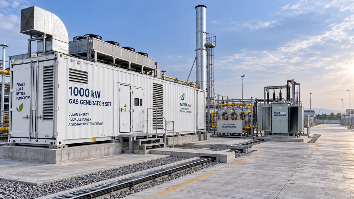
- Site infrastructure: gas skid, transformer, switchgear, stack, cable routes, drainage, access road, and safety separation.
In practice, a 1 MW container may occupy roughly 30–35 m², while a workable installation zone often grows to approximately 100–200 m² or more. The final area depends heavily on whether auxiliaries are integrated inside the enclosure, installed beside it, or placed in a separate equipment yard.
Clearance is driven by maintenance, not appearance
A containerized package is designed to reduce building work, but it is not designed to be pressed against a wall or fenced tightly on all sides. Service personnel need access to engine-side doors, control panels, batteries, filters, cooling components, and electrical cabinets. If major maintenance requires removal of a cylinder head, turbocharger, alternator component, or radiator section, the installation must also provide a practical lifting path.
As a preliminary rule, allow at least 1.5–2 m of accessible working space along service sides. Where enclosure doors swing outward, confirm their opening arc on the supplier’s general arrangement drawing rather than assuming a generic corridor is sufficient. The end containing the electrical output, gas connection, or control interface may need extra room for cable bending radius, valve operation, and panel access.
For sites where a forklift, mobile crane, or maintenance truck will be used, keep a clear approach route to the container. This is easy to overlook in a densely planned oilfield pad or factory utility yard. An installation can meet minimum clearances on paper yet still make a major overhaul unnecessarily disruptive.
Ventilation can expand the required plot area
Gas engines reject a substantial amount of heat. In a containerized configuration, that heat is managed through radiator cooling, ventilation fans, intake louvers, ductwork, or a remote cooling arrangement. The air path must remain unobstructed throughout the operating life of the equipment.
Assess the location of cool-air intake and hot-air discharge carefully. If hot discharge air is pulled back toward the intake, ambient temperature inside the enclosure can rise, reducing engine output margin and increasing stress on components. Nearby buildings, walls, container stacks, sound barriers, and prevailing wind direction all affect this risk.
Where the genset is installed in a confined yard, a remote radiator or ducted cooling solution may be preferable. It uses more site area and adds installation complexity, but it can solve recirculation problems that a compact layout cannot. The same principle applies when several units operate in parallel: airflow interaction between containers should be reviewed as part of the overall plant layout.
Plan space for the equipment outside the container
Some 1000 kW packages incorporate many auxiliaries within the enclosure. Others rely on external equipment selected according to gas quality, electrical architecture, runtime, emissions requirements, and local regulations. The assessor should request a battery-limit list early, because these items are often what change the land requirement.
If electrical redundancy is important, several smaller gas generator modules can sometimes offer a more flexible layout than one large unit. For example, a 500kW natural gas generator set configured as two 250 kW units can support staged loading and maintenance planning in suitable applications. However, modularity does not automatically reduce the plot requirement: it can add more clearances, cable connections, and airflow interfaces. The decision should be based on load profile, availability objectives, and site constraints rather than container count alone.
Foundation and access requirements affect the civil footprint
The generator container normally requires a level, engineered foundation capable of supporting both static weight and operating loads. Depending on the supplier’s design, this may be a reinforced concrete slab, strip foundations, steel beams, or another approved support arrangement. The foundation should include drainage provisions so water does not collect around doors, cable entries, or gas equipment.
Beyond the concrete pad, account for transport and installation. A 40-foot containerized genset arrives as a heavy load, and the route from the site entrance to the final pad must accommodate trailer turning, ground bearing capacity, overhead restrictions, and crane positioning. A difficult delivery route can force costly temporary works even when the final operating plot is relatively small.
Noise, exhaust, and safety boundaries should be drawn early
Acoustic containers help control generator noise, but they do not eliminate the need for site-level noise assessment. Intake and discharge openings, exhaust outlets, transformer hum, and reflected sound from hard surfaces can influence the property boundary. If the installation is near offices, residences, control rooms, or worker accommodation, reserve space for barriers or reconsider orientation before construction begins.
Safety separation must follow applicable local codes, project specifications, and the equipment manufacturer’s instructions. Gas piping and emergency shutoff devices should remain accessible. Exhaust outlets should be routed away from air intakes, occupied areas, and combustible materials. Fire detection, emergency stops, ventilation shutdown logic, and hazardous-area classification may also influence where supporting equipment can be placed.
A practical planning allowance for technical evaluation
For a preliminary feasibility study, it is reasonable to begin with a container body around 12 m × 2.5 m, then reserve working corridors around the enclosure and dedicated areas for auxiliaries. A rectangular equipment zone of roughly 15–18 m by 8–12 m is often a more realistic starting point than the 30 m² container footprint alone. This is not a final engineering dimension; remote cooling, multiple generator modules, transformer placement, strict noise limits, and local fire rules can increase it substantially.
The most reliable approach is to obtain the supplier’s general arrangement drawing, weight distribution, ventilation diagram, gas connection details, electrical single-line diagram, and maintenance access requirements. AMICO’s experience in gas power control, gas generation equipment, oilfield engineering, and distributed-energy applications is particularly relevant where the generator must interface with field gas, variable loads, and remote operating conditions.
Ultimately, the right site size for a 1000kW Containerized GasGenset is the space required for dependable operation—not merely the space required to set down a container. A layout that protects airflow, preserves maintenance access, and leaves room for safe electrical and gas connections will usually deliver a far more predictable project outcome than one optimized only for the smallest possible footprint.

Contact Us
Please use the form below to contact us.
If you require a response, we will contact you as soon as possible.