


Containerized 300 kW gas generation is growing in temporary power projects
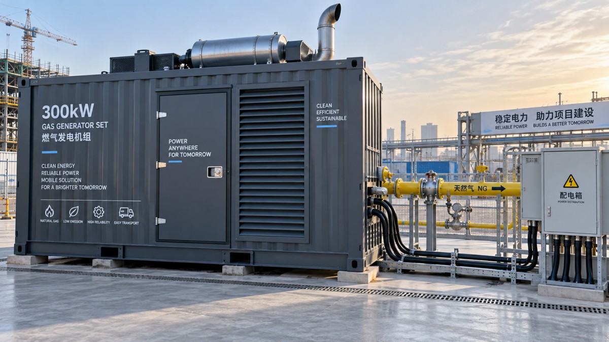
Temporary power projects often fail at the interfaces rather than at the generator itself: fuel arrives with a different quality than expected, the electrical load changes faster than the engine can stabilize, or a container is placed where airflow and service access are restricted. Containerized 300 kW gas generation is becoming more common because it packages the engine, alternator, controls, cooling equipment, gas train, acoustic treatment, and protection systems into a transportable unit that can be commissioned without building a permanent power house.
A 300 kW class package fits a useful middle range. It can carry a substantial construction load, support isolated oilfield equipment, cover a temporary utility gap, or operate as a distributed power block alongside other sources. Its value is not simply its rated output. The practical question is whether it can maintain acceptable voltage, frequency, and engine condition while operating on the actual fuel supply and load profile at the site.
Why the container format suits temporary installations
Temporary projects have compressed schedules and uncertain site conditions. A skid-mounted generator may still require separate weather protection, cable routing, exhaust work, acoustic treatment, and control-panel arrangements. A containerized configuration brings many of these elements together before shipment. That reduces the number of field interfaces, which is often more meaningful than reducing the number of installation days on paper.
The enclosure also protects equipment during repeated relocation. Road transport, crane handling, dust exposure, rain, and uneven staging areas put stress on external pipework, cable connections, radiators, and panels. A properly engineered container uses internal supports and restrained routing so that these components do not rely on their own connections to absorb transport vibration. Door placement matters as well. Access is needed for daily inspection, filter replacement, valve operation, battery work, and major service without moving the entire unit.
Containerization does not eliminate site preparation. The foundation or temporary support surface still needs enough bearing capacity and levelness to prevent frame distortion and vibration problems. The selected location must leave clearance for cooling-air intake and discharge. Placing a unit tightly against a wall, beneath a low canopy, or beside another hot-running machine can recirculate warm air through the radiator. The result may look like an engine cooling issue even when the cooling circuit is functioning correctly.
Rated output is only the starting point
The 300 kW rating should be read alongside the expected duty pattern. A stable load made up of pumps, resistive heating, and continuously running process equipment creates a different operating environment from a camp load with frequent motor starts, welding equipment, compressors, and intermittent auxiliaries. Two sites can show the same average demand while imposing very different transient requirements.
Motor starting deserves early attention. Large direct-on-line motors can create a brief voltage dip that affects controls, lighting, variable-speed drives, and other connected equipment. The relevant assessment includes motor starting method, starting sequence, cable length, transformer impedance, generator reactance, and the response of the engine governor. Adding a soft starter or variable-frequency drive may reduce the electrical shock, but it can introduce harmonic effects that should be considered with the alternator and control system.
Low-load operation can also be misunderstood. A gas engine is not automatically well matched to a project merely because the maximum expected demand is below 300 kW. Prolonged operation far below the intended load range can reduce fuel efficiency, allow unstable combustion under certain fuel conditions, and make a temporary installation appear uneconomical. Where the project alternates between low overnight demand and higher daytime demand, parallel units, load management, or a smaller night-load source may provide a better operational fit than one oversized package.
Fuel quality changes the technical answer
Gas availability is often described too broadly. “Natural gas,” “associated gas,” “biogas,” and “field gas” are categories, not complete fuel specifications. The engine requires usable energy content, pressure within the gas train's operating range, and contaminant levels that the equipment can tolerate. Variation in methane content changes the energy delivered per unit volume. A system sized around one calorific value can lose available output when the supplied gas becomes leaner.
Pressure stability is equally important. A gas line that appears adequate while the engine is unloaded can fall below the control requirement when demand rises. Long pipelines, undersized valves, restrictive filters, regulator behavior, and simultaneous gas consumers can all cause this condition. Symptoms may include slow load acceptance, unstable speed, alarms during step loading, or repeated shutdowns that are incorrectly attributed to the engine.
Biogas projects require additional attention to moisture and corrosive components. Condensate can accumulate at low points in piping and travel toward the gas train if drainage is poorly arranged. Hydrogen sulfide and siloxanes, where present, affect material selection, lubrication condition, and maintenance planning. For industrial or agricultural sites using locally produced fuel, the operating comparison may extend beyond 300 kW equipment to a 400kw biogas generator set when the available gas flow, site demand, and future load profile justify a larger biogas-based block. The comparison should still begin with fuel analysis and usable gas volume rather than nameplate capacity.
Electrical integration should be defined before delivery
A temporary power package is frequently connected to equipment that was not designed as a unified system. Existing switchboards, transformer arrangements, neutral grounding methods, protection settings, and remote control requirements can differ from the generator package assumptions. A clear single-line diagram avoids late changes to breakers, cable terminations, or protection logic.
When the generator operates independently, load shedding and priority circuits determine what happens during overload or a major step change. When it operates alongside the grid or another generating source, synchronization, reverse-power protection, export limitation, and islanding behavior need to be defined as part of the installation design. These are not interchangeable modes. A package intended only for isolated operation cannot be assumed ready for parallel duty without the relevant controls, switchgear, sensing, and commissioning work.
Cable selection is another recurring source of avoidable delay. The conductor size must account for current, installation method, ambient temperature, grouping, voltage drop, and termination space. Temporary cable runs are particularly vulnerable to physical damage, water ingress, and poor mechanical support. Routing should prevent vehicle traffic from crushing cables and keep high-current conductors separated from sensitive communication wiring where interference is a concern.
What affects lifecycle value during a short project
A temporary project may last months rather than years, yet lifecycle value still depends on more than rental period or purchase price. Fuel consumption at the real operating load, planned maintenance intervals, oil and filter availability, site access for service, transport frequency, and the cost of unplanned downtime all influence the result. A lower initial package price can be offset by a gas system that requires repeated adjustment or by an enclosure that makes basic maintenance difficult.
- Transport readiness: lifting points, forklift pockets where applicable, internal component restraints, and external connection protection should match the planned logistics route.
- Environmental fit: ambient temperature, dust, altitude, rain exposure, and acoustic limits influence cooling margin, filtration, enclosure design, and allowable output.
- Commissioning scope: fuel pressure verification, insulation testing, phase rotation, protective relay settings, no-load checks, and staged loading should be assigned before the unit arrives.
- Service access: a container that runs well with doors closed still needs sufficient clearance around service doors, radiator sections, exhaust components, and electrical cabinets.
The most reliable temporary installations treat the container as a complete but site-dependent system. Output stability comes from matching the generator, fuel supply, electrical network, cooling environment, and operating sequence. When those interfaces are defined early, a containerized 300 kW gas generator can move from transport asset to dependable project power with far fewer field modifications.

Contact Us
Please use the form below to contact us.
If you require a response, we will contact you as soon as possible.