


How Exhaust Treatment Affects Generator Room Ventilation Design
How Exhaust Treatment Affects Generator Room Ventilation Design
In generator room planning, the hard part usually starts when emissions control is added late in the design. On paper, exhaust treatment sits on the discharge side of the engine. In the room, it changes airflow resistance, radiant heat, maintenance access, and sometimes even the location of intake louvers. That is why exhaust treatment is not just an aftertreatment issue. It reshapes the ventilation strategy around the engine package.
The first design mistake is treating the exhaust line as if it only carries gas out of the building. Once oxidation catalysts, silencers, thermal insulation, or particulate-related components are introduced, the exhaust path becomes a heat source inside the room and a pressure-loss element in the overall system. If that added load is ignored, the ventilation fan may still meet nameplate airflow, yet the generator room runs hotter than expected, especially around the alternator end, cable trays, and service aisle.
This shows up differently in different projects. In a compact indoor plant with limited wall openings, the room often depends on forced intake and forced extraction. Here, exhaust treatment equipment can crowd the high-level space where hot air wants to accumulate and leave. In a larger industrial building with generous roof volume, the problem is less about total room temperature and more about localized heat pockets near the exhaust manifold, flexible joints, and treatment housing. Both rooms may have the same engine rating, but the ventilation layout challenge is not the same.
A useful question during layout review is simple: where does the aftertreatment hardware sit relative to the engine-driven cooling air path? If the treated exhaust line crosses above the radiator discharge zone or sits close to the combustion air intake route, ventilation performance can degrade even when duct sizing looks reasonable. The airflow pattern matters more than the fan catalog alone.
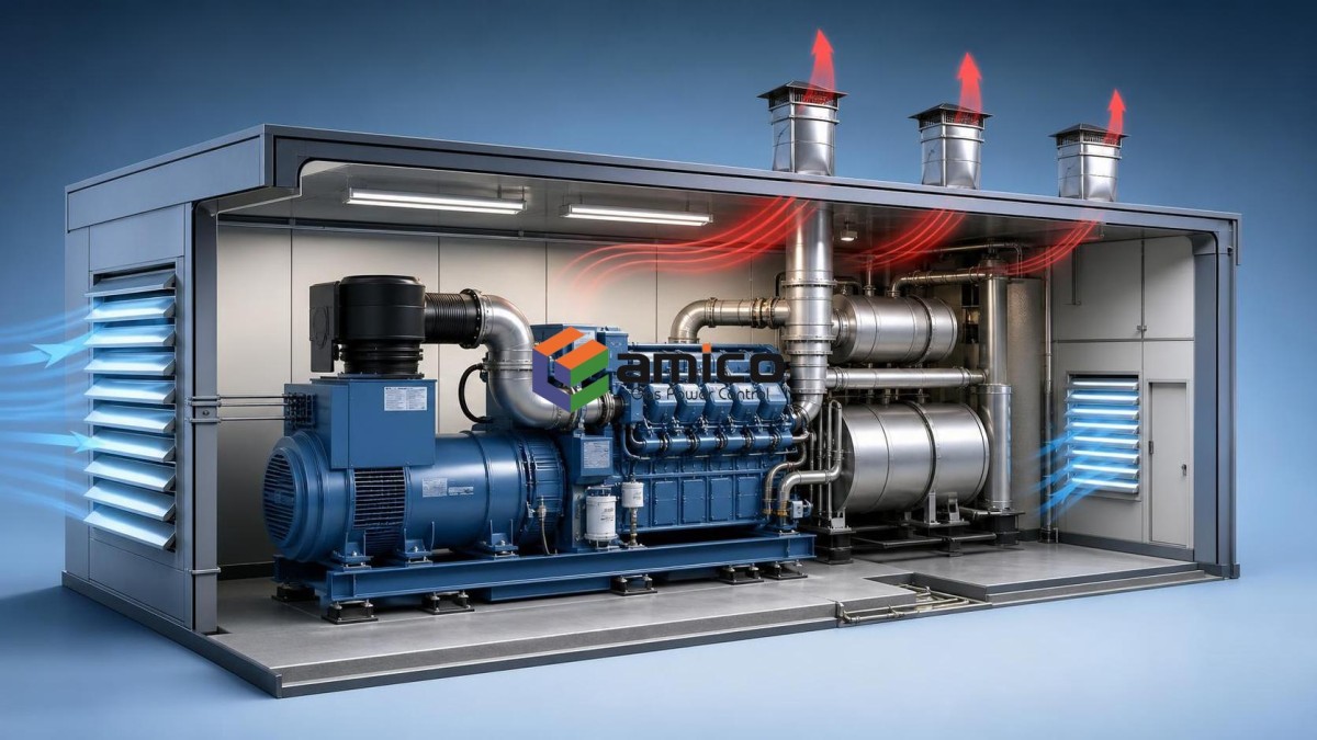
Heat Is Usually the Hidden Constraint
Exhaust treatment tends to raise surface temperatures in areas that operators must still access for inspection. Even when insulation is specified, real rooms rarely behave like ideal thermal diagrams. Clamps loosen, insulation jackets are removed for service and reinstalled imperfectly, and heat radiates into corners with poor air movement. In smaller generator rooms, that extra heat can push ambient conditions beyond what the control panel, battery charger, or cable insulation sees as comfortable.
This is one reason experienced teams separate two calculations that are often mixed together: engine cooling airflow and room heat removal. The engine package may already have a defined radiator airflow requirement, but exhaust treatment adds a separate thermal burden to the space. If both are folded into one rough estimate, the resulting design can look adequate while still leaving maintenance zones too hot for reliable operation.
Biogas projects make this more sensitive. Gas quality can vary, and treatment systems upstream of the engine do not eliminate every operating variable. Where a biogas set is installed indoors, ventilation design should leave some tolerance for changing exhaust temperatures and service conditions instead of assuming one perfectly stable operating point. That is relevant for units such as the 160kW biogas generator, especially when the room also contains gas handling equipment, cable routing, and auxiliary skids competing for the same footprint.
Pressure Loss Changes More Than the Exhaust Pipe
There is also a design chain reaction that gets missed in early coordination. Exhaust treatment components increase backpressure, so pipe routing often becomes more deliberate: fewer bends, shorter runs, better support, cleaner condensate handling. Once the route changes, ventilation openings often have to move as well. A louver that looked well positioned in the architectural drawing may now sit too close to a hot exhaust section, or a fan may discharge into an area where service access is needed for catalyst inspection.
That is why generator room ventilation should not be finalized before the exhaust treatment concept is at least broadly defined. Waiting until later usually leads to one of three compromises: larger fans with higher energy use, awkward ductwork that is difficult to maintain, or hotter working conditions accepted as “normal.” None of these is ideal, and all are more expensive to fix after installation.
In practice, projects with low ceiling height are often the most unforgiving. There is little vertical separation between hot exhaust hardware and the occupied service space. In those rooms, it may be more effective to focus on directional airflow and shielding of radiant zones than on simply increasing air volume. More airflow does not automatically solve recirculation.
What Usually Needs Checking on Site
Before finalizing the ventilation arrangement, several site conditions deserve a direct check rather than a drawing-room assumption:
- Whether the exhaust treatment assembly sits inside the room, in a separate enclosure, or partly outdoors.
- How much maintenance clearance is required around silencers, catalyst housings, drains, and flexible sections.
- Whether intake air can short-cycle to the extract side without passing through the engine and hot equipment zones.
- If gas safety devices, cable trays, and control cabinets are being placed in the same hot upper volume.
- How filter cleaning and fan maintenance will be performed after the exhaust system is in place.
These checks sound basic, but they often decide whether the room remains practical after a year of operation. The ventilation design that works on commissioning day is not always the one that remains workable after repeated service access around hot exhaust parts.
For distributed energy sites, where the room is part of a larger utility area rather than a stand-alone power house, layout discipline matters even more. AMICO’s work across gas power equipment, distributed power applications, and oilfield-related service environments reflects a common reality: the generator room is rarely an empty box built only for airflow. It shares space with fuel treatment, electrical systems, controls, and operating pathways. Exhaust treatment therefore has to be considered as part of the room ecosystem, not as an isolated component added after the generator selection.
Ventilation Decisions That Age Better
Some design decisions are consistently easier to live with. Keeping the exhaust treatment route compact but accessible is one. Preserving a clean airflow path from intake to heat sources to discharge is another. A third is leaving enough room to inspect supports, insulation, and joints without forcing technicians to work in the hottest stagnant zone of the room.
Where a project uses a biogas unit such as model AMC160GFJ-PZ, rated at 160kW (200kVA) and 400V, the ventilation review should account not only for engine cooling and general room extraction, but also for how the exhaust treatment arrangement influences serviceability over time. That matters more than many teams expect because a room that is difficult to access tends to be a room where thermal and exhaust-related issues are discovered late.
A good generator room is not defined by the largest fan or the most elaborate ducting. It is the one where exhaust treatment, airflow direction, equipment spacing, and maintenance logic still make sense when the plant is hot, loaded, and due for service. That is usually the point where ventilation design stops being a drawing exercise and starts showing whether the room was actually engineered for operation.

Contact Us
Please use the form below to contact us.
If you require a response, we will contact you as soon as possible.